Overview
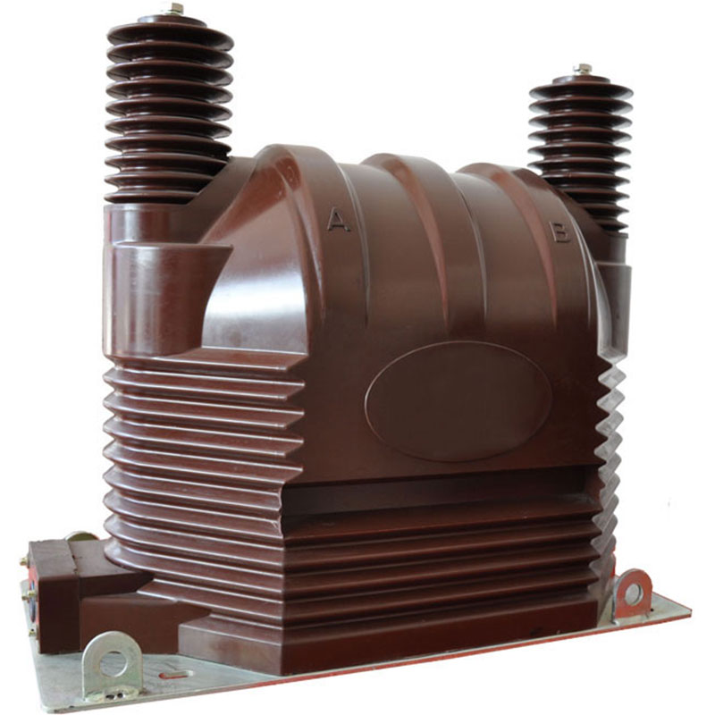
This product is suitable for indoor 33kV, 35kV, 36kV, AC system metering and protection.
The product can be used independently or installed in complete sets of cabinets and substations.
The current transformer adopts high-voltage epoxy resin, imported silicon steel sheet iron core, the winding adopts high-insulation enameled copper wire, and the winding and iron core are treated with high-quality semiconductor shielding paper.
Basic Structure
The basic structure of the voltage transformer is very similar to that of the transformer. It also has two windings, one is called the primary winding and the other is called the secondary winding. Both windings are mounted or wound around the iron core. There is insulation between the two windings and between the windings and the iron core, so that there is electrical isolation between the two windings and between the windings and the iron core. When the voltage transformer is running, the primary winding N1 is connected to the line in parallel, and the secondary winding N2 is connected to the instrument or relay in parallel. Therefore, when measuring the voltage on the high-voltage line, although the primary voltage is high, the secondary is low-voltage, which can ensure the safety of operators and instruments.
Precautions
1. Before the voltage transformer is put into operation, the test and inspection shall be carried out according to the items specified in the regulations. For example, measuring polarity, connection group, shaking insulation, nuclear phase sequence, etc.
2. The wiring of the voltage transformer should ensure its correctness. The primary winding should be connected in parallel with the circuit under test, and the secondary winding should be connected in parallel with the voltage coil of the connected measuring instrument, relay protection device or automatic device. At the same time, attention should be paid to the correctness of the polarity. .
3. The capacity of the load connected to the secondary side of the voltage transformer should be appropriate, and the load connected to the secondary side of the voltage transformer should not exceed its rated capacity, otherwise, the error of the transformer will increase, and it is difficult to achieve the correctness of the measurement.
4. No short circuit is allowed on the secondary side of the voltage transformer. Since the internal impedance of the voltage transformer is very small, if the secondary circuit is short-circuited, a large current will appear, which will damage the secondary equipment and even endanger personal safety. The voltage transformer can be equipped with a fuse on the secondary side to protect itself from being damaged by a short circuit on the secondary side. If possible, fuses should also be installed on the primary side to protect the high-voltage power grid from endangering the safety of the primary system due to the failure of the transformer’s high-voltage windings or lead wires.
5. In order to ensure the safety of people when touching measuring instruments and relays, the secondary winding of the voltage transformer must be grounded at one point. Because after grounding, when the insulation between the primary and secondary windings is damaged, it can prevent the high voltage of the instrument and the relay from endangering personal safety.
6. Short circuit is absolutely not allowed on the secondary side of the voltage transformer.

